TABLE OF CONTENTS
- Products Covered
- Summary
- Step 1: Mount the PoE Splitter to the Silver Mounting Plate
- Step 2: Mount your Peplink Router
- Step 3: Connecting Patch Cables
- Step 4: Cap the 2nd Ethernet Port
- Step 5: Build the Power Supply Cable that goes from the PoE Splitter to both the Starlink Dish and the Pepwave
- Step 6: Build Starlink Ethernet Cable (w/ waterproof connector)
- Step 7: Test For Power
- Step 8: Attach Middle Layer Tray to Max S Base Layer
- Step 9: Install the Starlink Dish
- Step 10: Attach Top Layer Tray and Complete the Install
- Step 11: Build Waterproof Connector for PoE Cable
- Installation Video
- Requesting Assistance
Products Covered
- Peplink Antenna Max S Enclosure
- Starlink Mini
- Compatible Peplink routers
- BR1 Mini Series
- Transit Series
- BR1 Pro Series
- 90W PoE Injector
- 90W PoE Splitter
Summary
This article will cover the step-by-step assembly instructions for setting up the Antenna Max S to run on PoE.
Pro Tip: We highly encourage you to watch the Max S build video at the bottom of this article before building your enclosure. It's a long video, but that's because it's thorough and covers a lot of important details. The Max S is not easy to take apart after it's fully assembled. This is a build that you will want to get right the first time.
Step 1: Mount the PoE Splitter to the Silver Mounting Plate
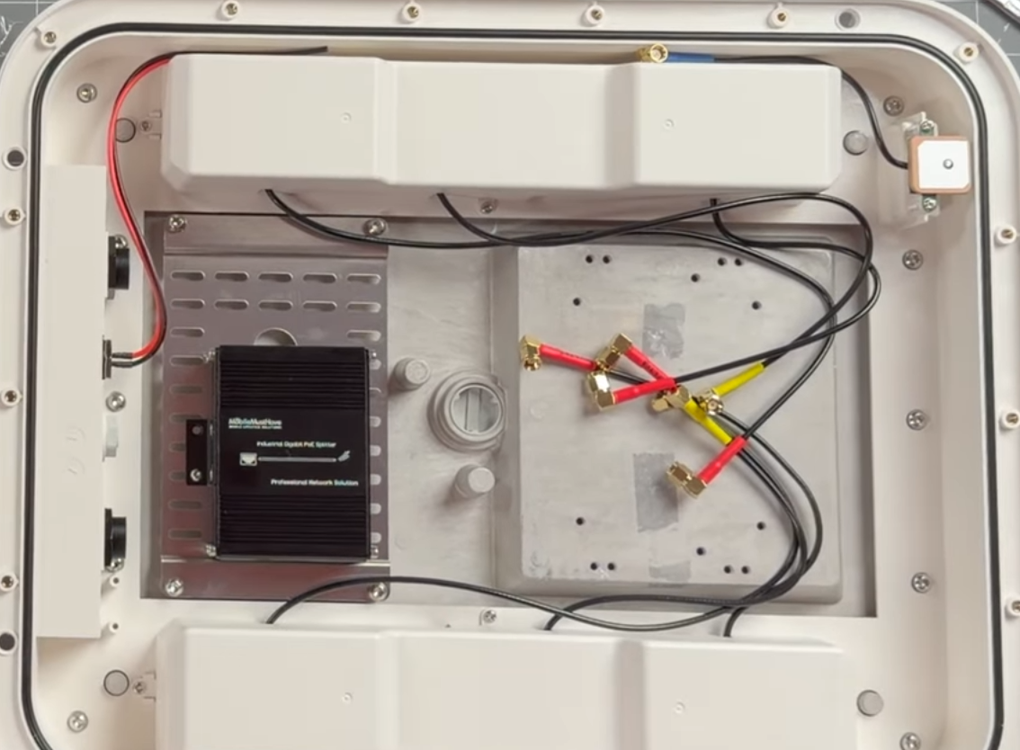
Key Points:
- You MUST remove the DIN rail mount from the splitter before you mount it to the plate.
- At the time of the writing of this article the included power cable for the router is very short, so you will need to position the splitter on the mounting plate in the same orientation as shown in the picture above in order for that cable to reach both the splitter and the router.
- We recommend using a piece of VHB tape (not included) to stick the splitter onto the mounting plate. Then you can reinforce the tape with a single screw to keep the splitter connected to the plate.
- BR1 Mini Series ONLY-If you're putting a BR1 Mini router inside the enclosure, you won't be using the GPS cable that comes preinstalled in the Max S, so you can tuck it out of the way - as shown in the upper right corner of the photo above.
IMPORTANT: Since we're powering the enclosure via PoE, you won't be using the DC power wires that come preinstalled in it (red and black wires on the upper left-hand side in the photo above). The tips of those wires should cut and wrapped in electrical tape. Then they can be tucked out of the way-as shown in the photo above.
Step 2: Mount your Peplink Router

Key Points:
- The Ethernet ports on the router should face the splitter.
- Use the predrilled mounting holes to mount the Peplink router opposite the splitter (there are holes for all 3 compatible Peplink router models).
- Connect the Max Ss Wi-Fi cables to the Wi-Fi ports on the router, the cellular cables to the cellular ports, and the GPS cable (if applicable) to the GPS port.
- For the cell cables and ports: connect cable 1 to port A, 2 to B, 3 to C, and 4 to D
- If you're installing this on a vehicle you WILL want to wrench-tighten the cable connectors to the ports, or you run the risk of them becoming disconnected due to vibration. Don't overtighten (you don't want to break the connectors), but hand tightening will likely not be enough.
Step 3: Connecting Patch Cables

Key Points:
- Connect the included Peplink patch cable to both the preinstalled ethernet port on the inside of the Max S (upper left) and to the PoE-IN port of the Splitter.
- Connect the 12" Patch cable that you bought from MMH, to both the LAN port on your Peplink router and to the Ethernet port on the splitter.
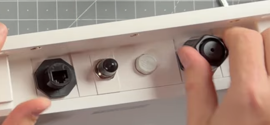
Step 4: Cap the 2nd Ethernet Port
Step 5: Build the Power Supply Cable that goes from the PoE Splitter to both the Starlink Dish and the Pepwave
What you'll need for this step:
- M25 Cable Gland w/ Starlink power cable. These will both come in a bag that was included in your Max S kit. There are 2 bags like this. One has an M25 gland with a wider hole and an ethernet cable, while the other has an M25 gland with a smaller hole and a thinner power cable. For this step, you'll only need the bag with the thinner power cable:

- Peplink power cable with 4-pin molex connector (included in Max S kit)

- POE Splitter Direct Wire Power Terminal
- Ferrule Crimper (optional)
Directions:
- Feed the Starlink power cable through the M25 gland (going from the top of the cap down)
- Open the bag containing the Peplink power cable with the 4-pin molex connector
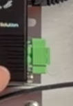
- Insert wires from BOTH the Starlink power cable and the Peplink power cable into the green POE splitter direct wire power terminal.
- Insert both red wires (one from each cable) into the positive terminal slot (labeled "V")
- Insert both black wires into the other (negative) terminal slot
- Tighten terminal screws to secure wires
- PRO TIP: If you want your installation to look nice and clean, use a ferrule crimper to crimp the positive and negative wires from each cable together before inserting them into the terminal.
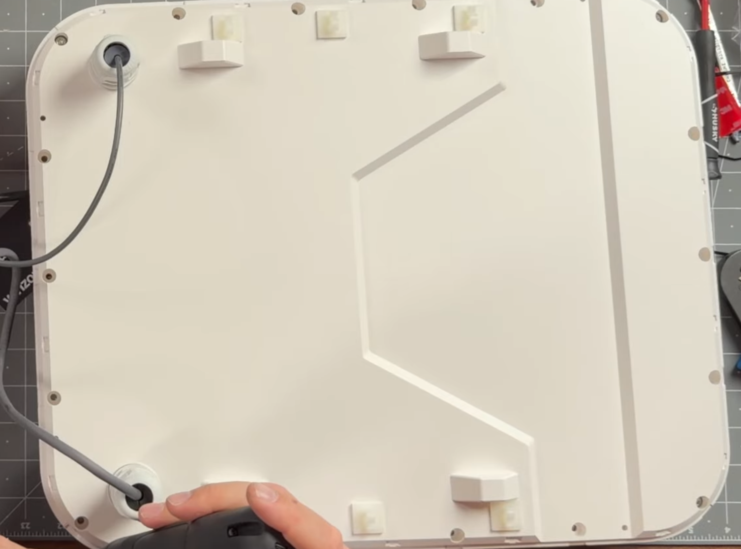
- Run the Starlink power cable through one of the 2 holes in the Max S's waterproof middle layer (we recommend using the hole on the lower left hand side-if you're facing the side with ethernet ports).

- Hand-tighten the lower plastic nut on the M25 cap onto the middle layer tray but leave the top nut loose so you can adjust the length of the power cable later when you plug it into the dish.
- Plug the green terminal connector into the PoE splitter. Tighten screws with mini screwdriver to ensure the terminal stays put.
- Plug the 4-pin molex connector into Pepwave
Step 6: Build Starlink Ethernet Cable (w/ waterproof connector)
Directions:
- Open bag containing other M25 gland and the Starlink ethernet cable
- Disassemble M25 connector and its waterproof connector into 4 individual pieces, like so:
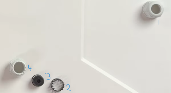
- You'll now reassemble those pieces around the Starlink ethernet cable to make the M25 pass through waterproof:
Key Points:- You'll be inserting each of the 4 components onto the end of the Starlink ethernet cable without the waterproof boot on it (in numerical order, right to left-referencing the photo above)
The end of the cable without the boot looks like this:
- The top of each component should be facing the other end of the cable (w/ the waterproof boot)
- The #3 piece in the photo above splits in half and gets put back together around the cable. It has one flat side, which should be facing the middle layer tray, not the Starlink dish.
- Connect parts 2 and 3 together on the cable 1st
- Then connect parts 1 and 4 together, around the newly connected 2 and 3
- Be careful not to cross thread 1 and 4 when you hand tighten them together
- Don't overtighten when you connect 1 and 4. You'll want to leave enough slack so you can slide the connector to the right spot on the cable.
- You'll be inserting each of the 4 components onto the end of the Starlink ethernet cable without the waterproof boot on it (in numerical order, right to left-referencing the photo above)
- Slide the non-waterproof end of the ethernet cable through the 2nd hole in the middle layer tray and connect the cable to the WAN port of the Pepwave:

Step 7: Test For Power
Before attaching the middle layer tray to the base and screwing it down, you'll want to ensure that both the Starlink dish and Pepwave are getting power.
Key Points:
- Connect your PoE Injector to a 12V power source (i.e. a house battery).
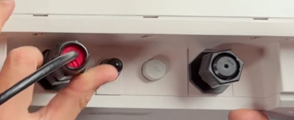
- Run an ethernet cable from the PoE injector to the PoE in port on the outside of the Max S (the one without the cap).
- Check to make sure that you have green Power and PoE lights on the Splitter.
- Check to make sure that the blue power light on the Starlink comes on.
- Check to make sure that the status light on the front of the Pepwave comes on and verify that it turns green before moving onto the next step.

Step 8: Attach Middle Layer Tray to Max S Base Layer
You're now ready to attach the middle layer and complete the assembly.
Key Points:
- The enclosure is directional; meaning that the tray can only be mounted one way. The holes with the Starlink cables will line up with the side of the enclosure that has the ethernet ports.
- When you go to attach the middle layer tray, be sure not to pinch any of the cables in the base layer. The tray should connect easily, and form a seal, if all of the wires and cables are out of the way.
- Apply the 18 provided screws to tighten the tray to the base layer.
- Important Tip: Be sure to apply screws in a cross pattern. This will evenly distribute the pressure you're applying to the waterproof seal.
Step 9: Install the Starlink Dish
Directions:
- Attach Starlink Mount (that came with your Starlink Mini) to the base of the Dish (don't apply screws yet):

- Gently set Starlink dish into top layer tray and connect both cables to the dish:
 Important note: The cables MUST be pushed to either side of the Starlink mount or the tray will pinch (and probably damage) the cables.
 - Apply the 4 screws in a cross pattern.
Step 10: Attach Top Layer Tray and Complete the Install
Directions:
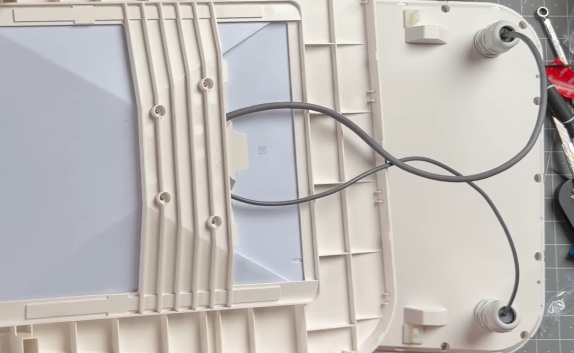
- Make sure you have enough slack on your 2 Starlink cables so that you can attach the top layer tray to the middle layer.
- Connect the cables to the chase run clips along the sides of the middle layer tray:

- Hand tighten M25 waterproof connectors:

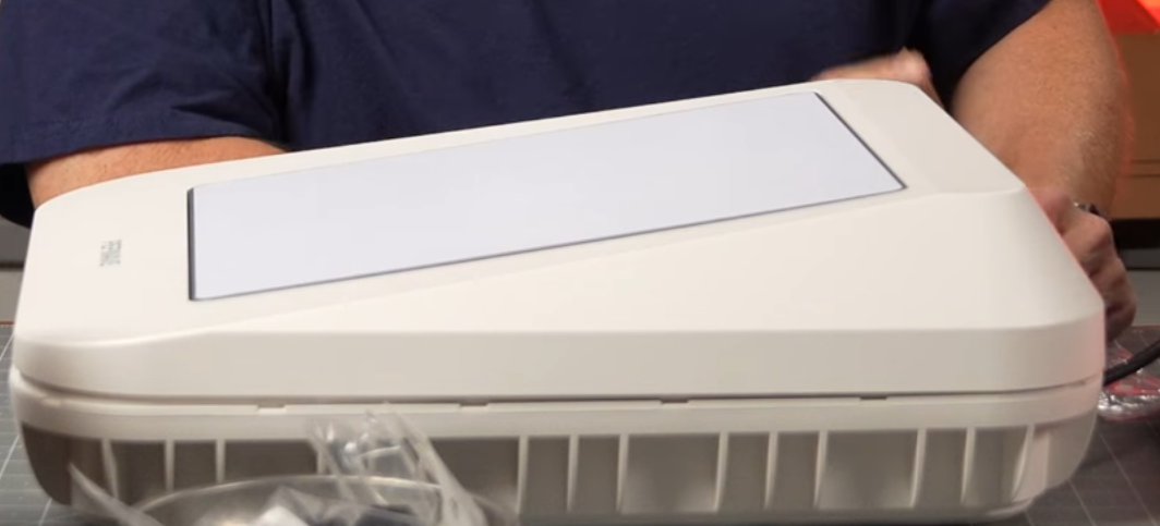
- The top layer is now (almost) ready to be connected to the middle layer:
Top Tip: Before you snap the top layer into place and complete your Max S build, we highly encourage you to complete your network setup. Once that top layer is clicked into place it will be difficult to get back into the unit. Power the unit back up and enable SpeedFusion, enable Starlink Support, etc. Once everything is set up to your liking you can snap the top layer into place.
Step 11: Build Waterproof Connector for PoE Cable
Directions:
- Assemble 4 connector pieces over the cable. See step 6 (it's exactly the same):

- Plug cable into the Max S's PoE in port
- Tighten the connector to create a waterproof seal:
Installation Video:
Requesting Assistance
If you feel you are not getting anywhere or there is another issue, you can always reach out to our team directly by initiating a ticket here on the support portal or by emailing info@mobilemusthave.com
Thank you for being the best part of MobileMustHave.com!
Was this article helpful?
That’s Great!
Thank you for your feedback
Sorry! We couldn't be helpful
Thank you for your feedback
Feedback sent
We appreciate your effort and will try to fix the article